Previous Work
Computer Vision algorithm optimization on FPGA
Log
After considering multiple options, I finally decided to rely on the EDAplayground online IDE and testbench to develop and test my first verilog modules. EDAplayground provides multiple advantages and a versatile development environment that for a while was enough to fit the early projects needs, but soon enough I met with some shortcomings that forced me to leave the platform and transition to a real FPGA.
The project is divided in Chapters with well defined objectives that aim to take steps to eventualy achieve complex image processing in an open source FPGA. Each chapter links to a folder with the source, diagrams and examples in this github repository
Alhambra II v1.0A
5 CAM VGA II
While migrating this project to the Alhambra II I stumbled with some pin issues, it seems the new design for the FPGA lacks 8 general purpose pings I was using to output some of the VGA signals in the Alhambra I.
4.5 VGA II
The new Alhambra II is ready for testing, I’ll implement the simpler “VGA” modules before moving on to the CAM-VGA.
Migrating the module to the Alhambra II was rather painless and everything seems to be working as intended with the same results as the [VGA] module in the Alhambra I
Alhambra I
4 CAM_VGA
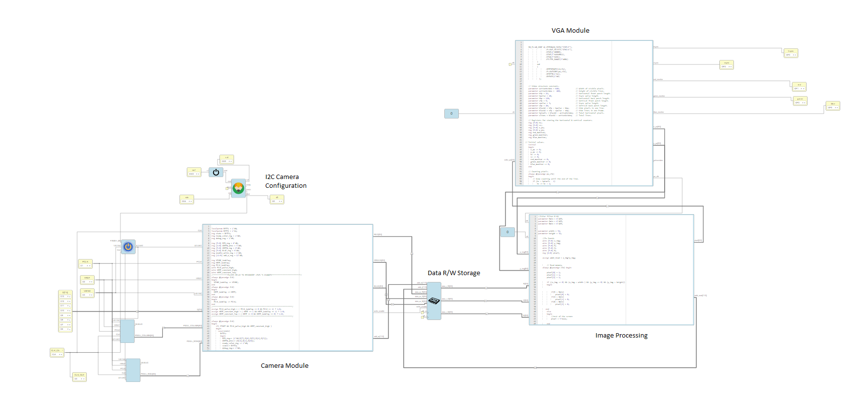
This Chapter’s main objective is to start using real input data from a camera instead of hex/bin images, finally creating a project capable of recording, processing and displaying live video with an open-source FPGA.
We decided to use an OV7670 camera for this purpose, as described in previous chapters, the Alhambra I has serious HW limitations so the default behavior of the OV7670 overwhelmingly outperforms our capabilities. This is why I’m using a modified version of the camera module, the data stored in the FPGA will be 18 bit per pixel (instead of 24bit per pixel) and only a 32x32 subset of the recorded image will be used for image processing and display.
Debugging has become a major issue as IceStudio doesn’t seem to be able to identify problems occuring in the modules and overall configuration, the modules code seems to verify but fails to build and no information is given. A simpler version of the camera recording modules is needed to at least make it work and through trial and error upgrade it to the intended final state:

####
</a>
####

It seems that the issue with IceStudio where compiling errors cannot be seen if they are part of a imported .ice module/file can be solved by “Unraveling” these modules so there is only a single .ice file. this allowed me to finally be able compile and upload the project to the FPGA.
However this didn’t improve the situation very much as the video capture part of the project isn’t working, the VGA display works fine though. There seems to be no imput for the Camera as if the I2C protocol that initilizes it isn’t working, a signal analyzer has become a necessity to be able to debug these behaviours.
With the help of a Logic Analyzer and Saleae Logic 1.2.18 software I was able to start sampling the different channels that feed and are fed to the OV7670 camera, Saleae Logic includes a I2C protocol decoder so the I2C communications can be seen in the next image:


At first glance it seemed that the I2C protocol was working as intended but sampling other channels like VSYNC (Vertical synchronization (Output)) and HREF (Horizontal synchronization (Output)) we can see that noise is polluting our signals…


It seems that the Icezum Alhambra I has some issues keeping clean signals so one solution would be to add pull-up resistors to the conflicting channels, I’ll be testing again once I get my hands on some of those. Nevertheless the limits of the Alhambra I have brought in constant problems that hinder progress in ways that are only laterally related to the purpose of this project, even though this allowed me to learn a lot, José María, Juan and I have decided that we need to transition to an Icezum Alhambra II, this FPGA was in part developed to fix some of these issues I’ve been strugling with so hopefully soon I’ll be making more progress towards our goal.
3 VGA
Finally manage to integrate a real VGA output to the verilog modules. Due to the HW limitations of the Icezum Alhambra the VGA output is limited in resolution, size and frame rate, this meant that input data needed trimming in order to be successfully stored, processed and displayed.
- Testing VGA module


binBatmanLogo is the first working example of VGA output. A simple binary map image of the batman logo is read from the bm.list file and its information published to the VGA module.


The batman logo could be displayed in color but it still was binary data so the output only displayed 2 of the 8 possible values. A new hex images was used with 24bits per pixel, as we can only display 8 bit color(3 bits per pixel) this was an ideal situation to implement simple RGB filters.
This project swaps the binary batman image to a RGB(24 bits per pixel) 32x32 hex image and displays through VGA a 3 bit per pixel version of it. Applying a color filter where pixels exceeding a 50% threshold on its RGB 8 bit values will be displayed as 1 or otherwise as 0, effectively translating from 16,777,216 colors to 8.


In the RGB8Colous project, the data processing was done on-the-go (read, processed and displayed). This behavior is enough for simple image processing but the aim of this project is to use more complex image processing like convolutions and complex filters. These operations require access to different parts of the images data at the same time, making storage a necessity.
In this project the module developed in Basics/RAM is integrated to provide storage reading and writing capabilities.
2 HexToVGA
In this Chapter I began the transition from the online IDE to the real FPGA Icezum Alhambra I. The size limit and the inability to write the data to a file were hindering progress so I adapted the code to Icestudio, all .v files became .ice files.
Even though this folder is named /HexToVGA, VGA output isn’t achieved in this chapter, what is achieved is automation of the image file reading, writing and encoding and working image processing(color filters)
I changed the input image format to .PPM which is way simpler than .bmp and allowed me to focus on the more important verilog modules,
A python script extracts the RGB hexadecimal values from the rainbow.ppm file into the dataSplit.hex file, this file is read into memory in the RGBgraphics.v module, the RGB values are filtered according to local parameters and finally written into a file. A script adds the ppm header to the filtered Hex values.
In HexToVGA/examples we can see the results for different RGB component filtering.


1 Basics
The different folders in /Basics had a simple objective, learn FPGA/verilog fundamentals and test some functionality that would be needed later. Mainly through online seminars, documentation (HDL/verilog), youtube tutorials and some examples the EDAPlayground community had uploaded to the platform I managed to familiarize with the HDL and eventually develop working examples that could simulate image data collection, processing and storage.
-
Verilog code and testbench testing some simple logic operations (AND, NOR, OR, etc)
-
A verilog module that implement simple data storage(ram.v) and a custom data storage to handle 24bit-RGB Data (rgb_ram.v)
-
A new module capable of reading hexadecimal data from an image file and store it in the RAM/rgb_ram.v module

Finally managed to do some simple Image Processing. Added a new module to the previous project that read the RGB data from the RGB_RAM Module and applied simple RGB filters to delete the R/G/B components from the hexadecimal data from the BMP image.

This test bench adds a new module for color filtering through the filter_X signals.
Even though the verilog modules worked as intended, as seen in the (raw) output data(what I believed to be the RGB hexadecimal values were actually filtered), after recreating the BMP file from the filtered HEX data the image wasn’t displaying the intended result.


—Filter R component—>


This problem aroused because EDAplayground forces a character/line limit to the files used in their online IDE and this limited the size of the input image I could use, this forced me to develop a new way to extract the hexadecimal values from the image. The script I was using only worked for a specific 768x512 image, so I had to develop my own solution to extract the data from a custom 32x32 image and the BMP file format proved to be a bit more complex than expected.
Long story short, after some headaches I noticed 2 issues, that the data in the 32x32 image I was using wasn’t RGB but RGBA and that correct encoding is really important when handling .bmp, .hex and raw files.
This issues are addressed in the next chapter, as image format and encoding aren’t the main focus of this project I transitioned to the simpler portable pixmap format(PPM) for the image and proccesing in both the actual FPGA and the online simmulator.
Documentation & Sources
FPGA:
FPGAs and Verilog HDL:
From Intel FPGA youtube channel(https://www.youtube.com/channel/UC0wEPiFb0J6AZZ3oPXRoRpw): -Verilog HDL Basics (https://www.youtube.com/watch?v=PJGvZSlsLKs): Brief overview of Verilog structure, terminology and syntax. -How to Begin a Simple FPGA Design(https://www.youtube.com/watch?v=bwoyQ_RnaiA)
From Synopsys youtube channel(https://www.youtube.com/channel/UCUiwwDJdlOIILWWCjPKLb9Q) SystemVerilog & UVM -Intro (https://www.youtube.com/watch?v=igYsB_sKeNc) -UVM Basics: (https://www.youtube.com/watch?v=WEA4Ds1WAh4)
Simmulation:
-Usefull info on testbenches http://www.drdobbs.com/embedded-systems/easy-verilog-test-benches/240166891
-List of HDL simulators(https://en.wikipedia.org/wiki/List_of_HDL_simulators)(including Open-Source):
Commercial: –Alteras ModelSim: seems to be one of the best and most popular but isn’t open-source. Yet it’s available in student, or evaluation/demo edition.
Free: –EDA Playground(https://www.edaplayground.com/): Online IDE Nice examples like “UVM Hello World Tutorial” https://www.youtube.com/watch?v=Qn6SvG-Kya0
Free & Open-source: Found two interesting solutions
– Icarus verilog (http://iverilog.icarus.com/): Verilog simulation and synthesis tool. ·Nice Fandom wiki https://iverilog.fandom.com/wiki/Main_Page ·Compatible with free waveform viewer (GTKWAVE)
–Verilator(https://www.veripool.org/wiki/verilator): converts Verilog to a cycle-accurate behavioral model in C++/C/SystemC.
-IDE:
Icestudio (https://alhambrabits.com/software/) Documentation(https://icestudio.readthedocs.io/en/latest/)
Image Processing:
https://en.wikipedia.org/wiki/Mathematical_morphology https://en.wikipedia.org/wiki/Digital_image_processing
Masks:
https://en.wikipedia.org/wiki/Kernel_(image_processing)
Convolution https://www.allaboutcircuits.com/technical-articles/two-dimensional-convolution-in-image-processing/